
How to Design for 3D Printing: The Ultimate Guide to Modeling, Software, and Preparation
Table of Contents
The plastic part snapped cleanly in half the moment I tried to screw it into place. I stared at the broken pieces in frustration—my first “real” 3D printed design, a custom bracket I’d spent hours modeling in CAD software, and it failed within seconds of real-world use. What went wrong? The model looked perfect on screen, sliced without errors, and printed beautifully. But I’d made the classic beginner mistake: I designed it like a traditional part without understanding how 3D printing’s layer-by-layer construction affects strength. The stress I applied pulled perpendicular to the print layers, the weakest direction, and my thin 1mm walls couldn’t handle it. That failure taught me the fundamental truth about learning how to design for 3D printing: it’s not just about creating 3D models—it’s about understanding the unique constraints and opportunities of additive manufacturing. Wall thickness minimums, overhang angles, layer orientation, support requirements, and material properties all influence whether your beautiful digital model becomes a functional physical object or expensive plastic waste. Mastering these principles transforms you from someone who makes models to someone who designs printable, functional parts.
How to design for 3D printing requires fundamentally different thinking than traditional manufacturing or pure digital modeling. Unlike CNC machining that removes material from solid blocks or injection molding that fills cavities with liquid plastic, 3D printing builds objects layer by layer from the bottom up, creating unique possibilities and constraints. This additive process enables complex geometries impossible in traditional manufacturing—internal cavities, organic shapes, integrated assemblies—but demands respect for physical realities like overhangs requiring support structures, minimum feature sizes determined by nozzle diameter, and anisotropic strength where parts are weaker between layers than within them. Understanding how to design a 3D model for printing means thinking about print orientation from the earliest concept stages, accounting for material shrinkage and warping, and optimizing geometry for both printability and intended function. Whether designing functional mechanical parts, artistic sculptures, replacement components, or prototype products, the principles remain consistent: design with the printing process in mind, not despite it.
This comprehensive guide explores how to design for 3D printing from fundamental principles through advanced techniques, covering essential software for creating 3D models, core design principles ensuring printability, step-by-step workflows from concept to print-ready files, optimization strategies for strength and material efficiency, and preparation requirements for successful printing. Whether you’re a complete beginner wondering how to design things for 3D printing or an experienced modeler looking to optimize designs for additive manufacturing, this guide provides the knowledge needed to create models that don’t just look good on screen but print successfully and perform their intended functions. As we’ll explore in depth through our cluster articles on software selection, design rules, advanced techniques, and even how to design a 3D printer itself, mastering 3D printing design opens unlimited creative and practical possibilities.
Understanding 3D Printing: How the Process Shapes Design
Before learning specific design techniques, understanding how 3D printing physically works illuminates why certain design principles matter.
The Layer-by-Layer Build Process
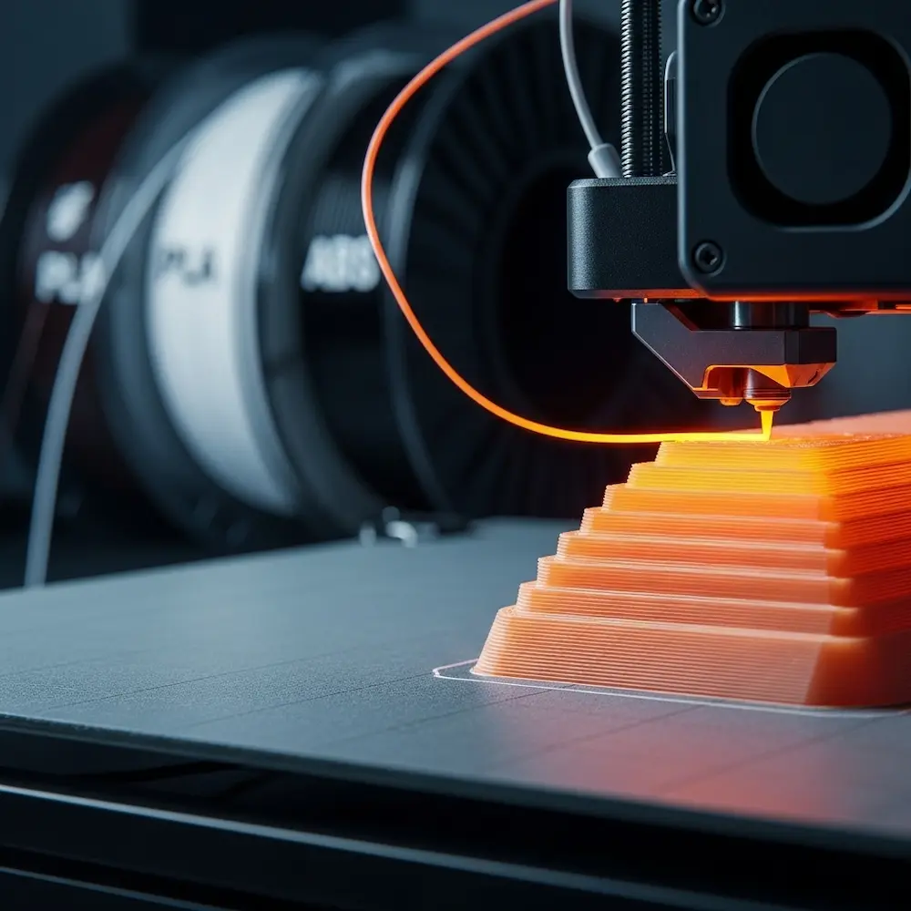
3D printing, specifically Fused Deposition Modeling (FDM)—the most common consumer 3D printing technology—builds objects by depositing melted plastic filament in thin horizontal layers. UltiMaker’s comprehensive guide explains: “3D printing builds objects layer by layer”. The printer head moves in X and Y axes, depositing material in patterns defined by your 3D model, then the build platform lowers (or the head raises) slightly, and the next layer deposits on top. This repeats hundreds or thousands of times until the complete object emerges.
Layer adhesion determines strength—and represents 3D printing’s fundamental structural characteristic. As Rahix’s technical blog notes: “3d-printed parts are much weaker in the direction of pulling apart the layers”. Each layer bonds to the previous one through heat fusion as new molten plastic contacts the layer below. This bond is strong but never quite as strong as the continuous plastic within a single layer. Consequently, parts experience anisotropic strength—they’re stronger along the X-Y plane (within layers) than along the Z-axis (between layers). Understanding this principle shapes every design decision about part orientation and geometry.
Print orientation affects everything. The blog emphasizes: “before starting on a design, you should first consider the direction of tensile forces in your part and use them to decide on a print orientation. All further design should then be done with this print orientation in mind”. A vertical cylinder and horizontal cylinder have identical geometry but dramatically different strength characteristics depending on how force applies. Learning how to design for 3D printing means thinking about orientation from the conceptual stage, not as an afterthought when preparing to print.
Material Behavior and Constraints
Different 3D printing materials exhibit distinct behaviors affecting design choices.
Common filament materials each have characteristics influencing design. PLA (Polylactic Acid) prints easily with minimal warping but offers moderate strength and poor heat resistance. ABS (Acrylonitrile Butadiene Styrene) provides better strength and heat tolerance but warps significantly and requires heated build chambers. PETG offers a middle ground with good strength, moderate ease of printing, and better layer adhesion than PLA. TPU and other flexible filaments enable rubber-like parts but require special design considerations for their elasticity. Understanding material properties helps you design parts optimized for their intended material.
Shrinkage and warping occur as printed plastic cools. The Zeal 3D Printing guide lists “Shrinkage and Warping” as a fundamental design consideration. Different materials shrink at different rates—ABS notably more than PLA—and this dimensional change can cause parts to curl away from the build plate (warping) or create dimensional inaccuracy. Large flat surfaces are particularly prone to warping. Effective designs minimize these issues through appropriate geometry, understanding which materials suit which applications.
Choosing the Right Software for 3D Printing Design
Software selection represents your first major decision when learning how to design 3D models for printing. Our comprehensive cluster article on design software explores this topic in depth, but understanding basic categories helps you start.
CAD Software for Functional Parts
Parametric CAD programs like Fusion 360, FreeCAD, and professional tools like SolidWorks excel at mechanical design. Autodesk’s 3D printing guide explains that Fusion 360 “combines advanced design, simulation, and manufacturing tools in a single solution, allowing users to create intricate and precise 3D models effortlessly”. These programs define models through dimensions and relationships, making them ideal for parts requiring precise measurements—brackets, enclosures, replacement components, and assemblies.
Beginner-friendly options lower the entry barrier. Tinkercad offers the most accessible introduction to 3D design. As Autodesk notes, “Tinkercad’s drag-and-drop functionality and pre-defined shapes enable beginners to quickly grasp the basics of 3D design”. The YouTube comparison lists it first among beginner software, emphasizing its web-based accessibility requiring no installation. For absolute beginners wondering how to design your own 3D prints, Tinkercad provides an excellent starting point.
Organic Modeling Software
Blender dominates free 3D modeling for artistic and organic forms. While primarily known as animation and rendering software, Blender’s powerful modeling tools suit sculptural designs, figurines, artistic objects, and anything requiring flowing organic shapes rather than precise mechanical dimensions. The beginner software video includes it specifically for this capability.
When to use each type: Autodesk’s guide recommends evaluating “Features and Capabilities” to “Make sure that the software offers essential tools for 3D modeling, such as parametric design, mesh editing, and support for complex geometries”. Use CAD for functional parts with precise dimensions; use organic modelers for artistic work.
Core Principles of Printable Design
Certain fundamental rules determine whether models print successfully. Understanding these principles before you design prevents the frustration of unprintable models.
Wall Thickness: The Foundation of Printability
Minimum wall thickness represents perhaps the most critical design parameter. Mandarin 3D’s detailed guide states emphatically: “The golden rule: Your minimum wall thickness should be at least twice your nozzle diameter. For the standard 0.4mm nozzle, that’s 0.8mm minimum”. Walls thinner than this minimum become weak, prone to gaps, or fail to print entirely.
Technology-specific minimums vary. Sinterit’s wall thickness guide provides detailed specifications: “FDM (PLA/ABS): ~0.8–1.2 mm, SLA/DLP: ~0.5 mm, SLS (Nylon PA12): ~0.7 mm for vertical walls, 1 mm for unsupported, DMLS (metal): ~1–2 mm”. These minimums reflect each technology’s capabilities and material properties. Most consumer FDM printers use 0.4mm nozzles, making 0.8-1.0mm practical minimums, though 1.2mm or thicker provides better reliability.
Optimal thickness for different applications balances strength, print time, and material cost. The Mandarin guide categorizes usage: for decorative models use 1.2-2.0mm walls with 10-20% infill; for functional parts use 2.0-3.0mm walls with 20-40% infill; for heavy-duty applications use 3.0-5.0mm+ walls with 50%+ infill. The guide notes: “Walls thicker than 5mm are rarely necessary for FDM prints unless you’re building something like a mold or fixture”. Understanding these guidelines helps optimize designs for their intended purpose.
Best practices from Sinterit’s guide include: “Stick to 2–3 times the nozzle diameter (FDM) or laser spot size (SLS/DMLS) as a baseline. Increase wall thickness for functional parts or objects that require post-processing (like sanding or polishing). Avoid long, thin, unsupported vertical or horizontal walls — they tend to warp or break easily”. These principles prevent common failure modes.
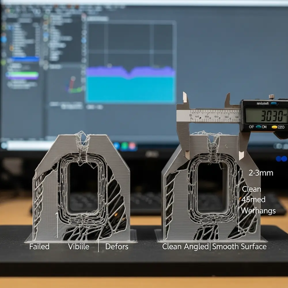
Overhangs and the 45-Degree Rule
Overhangs occur when part geometry extends outward without support directly below. The Zeal guide lists “Overhangs and Support” first among fundamental design considerations. When the 3D printer tries to deposit plastic in mid-air, it sags or fails completely.
The 45-degree rule provides practical guidance. As explained in the YouTube video “3D Printing Basics – The CORE Design Fundamental,” angles up to 45 degrees from vertical generally print without support, while steeper overhangs require support structures. Hydra Research’s design rules elaborate this principle with detailed guidelines for various overhang angles. Understanding this rule helps you design self-supporting geometry or intentionally place features where supports can be easily removed.
Design strategies to minimize supports include orienting parts to reduce overhangs, adding chamfers or fillets to reduce overhang angles, breaking designs into multiple pieces that print flat, and designing intentional support-touch points where supports can be cleanly removed. Our article on design rules explores these techniques comprehensively.
Feature Resolution and Detail Limits
Minimum feature size depends on your printer’s capabilities and chosen layer height. The Zeal guide notes: “The smallest feature size any 3D printing technique can handle must be considered while developing a 3D model with complex details. The chosen layer height and the characteristics and mechanics of every 3D printing method determine the minimal level of detail”. Tiny details below your printer’s resolution either won’t print or will merge into blobs.
Layer height affects detail. Common layer heights range from 0.1mm (high detail, slow) to 0.3mm (lower detail, fast). Features smaller than 2-3 layer heights become unreliable. Designing with your intended print settings in mind ensures details remain visible and distinct.
Manifold Geometry and Watertight Meshes
Watertight models (also called manifold meshes) are essential for successful 3D printing. This means the 3D model’s surface forms a completely closed volume with no holes, gaps, or internal faces. Non-manifold geometry confuses slicing software, creating errors or unpredictable results. UltiMaker’s guide emphasizes ensuring your design has proper manifold geometry.
Common manifold errors include coincident faces (two faces occupying the same space), edges shared by more than two faces, holes in the mesh, and inverted normals (faces pointing the wrong direction). Most 3D modeling software includes mesh analysis tools highlighting these problems. Fixing them before export prevents printing headaches.
Step-by-Step: How to Design a 3D Print Model
With principles understood, let’s walk through the actual design process. Our detailed cluster article on how to create a screen print design explores this workflow comprehensively, but key stages deserve overview.
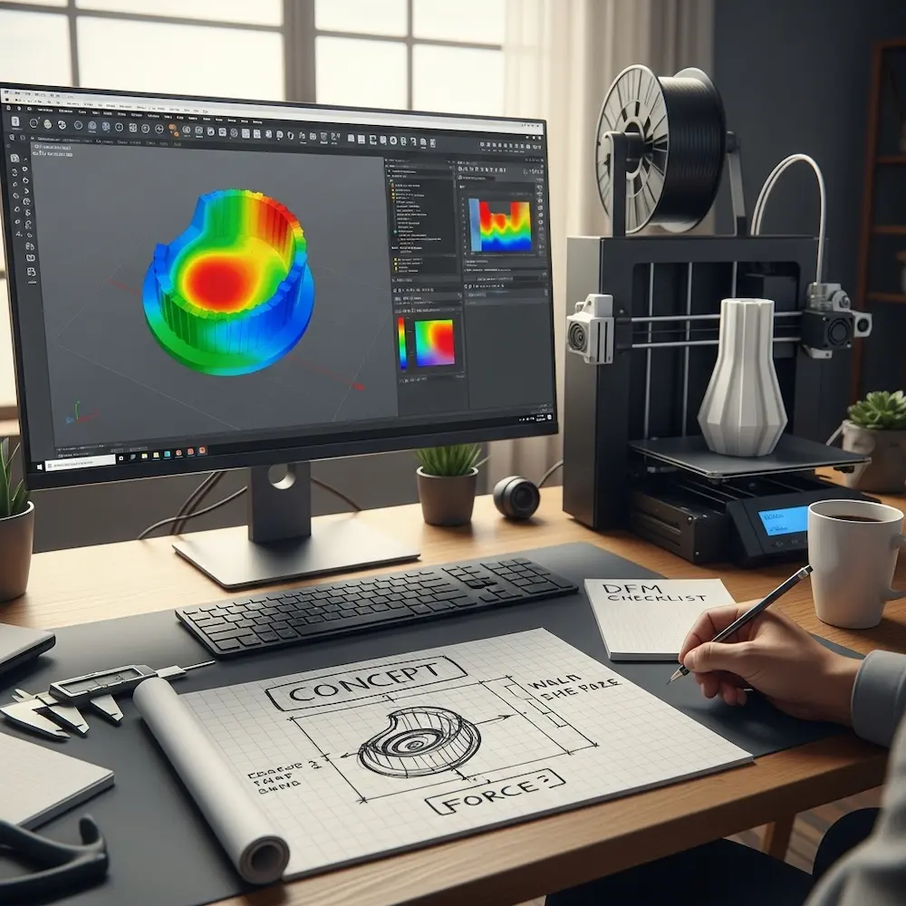
Stage 1: Concept and Planning
Define functional requirements before opening software. What problem does this part solve? What forces will it experience? What dimensions must it meet? The design-for-manufacturing blog emphasizes three considerations: “Design according to force— Parts should be designed such that their geometry is optimal for the forces it has to transmit and withstand. Design according to manufacturing method— Often called DFM (Design For Manufacturing), parts should be designed such that they are easy to produce. Design according to cost— Parts should be as cheap as possible. With 3d-printing, this means minimizing material use and print time”.
Determine print orientation. As noted earlier, orientation affects strength dramatically. Sketch or visualize how the part will be oriented on the print bed, considering where forces will apply and how to align strong in-layer strength with load directions. Making this decision early shapes all subsequent design choices.
Stage 2: Creating the 3D Model
Build with printability in mind from the first features. Don’t create a “perfect” design then try to make it printable—integrate printing constraints throughout the modeling process. This means checking wall thicknesses as you work, designing chamfers to reduce overhangs, and avoiding problematic geometry rather than fixing it later.
Use appropriate modeling techniques for your software. In parametric CAD, build from sketches defining 2D profiles, then extrude, revolve, or loft them into 3D shapes. Define relationships between features so dimension changes propagate properly. In organic modelers like Blender, sculpt forms using digital clay-like tools. Each approach suits different design goals.
Stage 3: Design Optimization
Analyze and refine your model before export. Check wall thicknesses throughout the model, examine overhangs and consider support requirements, verify all features exceed minimum size limits, and run mesh analysis tools to find and fix manifold errors. Fusion 360’s “simulation capabilities help identify and resolve potential issues before printing, ensuring optimal performance and reducing material waste”.
Consider print time and material costs. Can you hollow thick sections while maintaining strength? Can you reduce infill percentages in non-critical areas? The design blog emphasizes designing “according to cost”—with 3D printing, “this means minimizing material use and print time”. Strategic optimization reduces costs without sacrificing function.
Stage 4: File Export
Export in appropriate formats. STL (STereoLithography) files remain the standard for 3D printing, encoding your model as a mesh of triangular faces. Most 3D modeling software exports STL files directly. OBJ format offers an alternative supporting colors and textures, though most 3D printing uses STL. Creality’s guide covers export requirements: “We will cover everything from the idea to files ready for slicing”.
Export settings matter. Higher resolution (more/smaller triangles) captures curves and details better but creates larger files. For most prints, medium resolution balances quality and file size adequately. Ensure your software exports in correct units (millimeters are standard).
From Model to Print: Slicing and Preparation
Creating the 3D model represents only half the process—converting it to printer instructions requires slicing software.
Understanding Slicing Software
Slicers translate 3D models into G-code—the numerical control language 3D printers understand. Popular free slicers include Cura (from UltiMaker), PrusaSlicer, and Simplify3D (paid). These programs “slice” your model into horizontal layers and calculate toolpaths for the printer to follow.
Key slicer settings dramatically affect print quality and success. Layer height determines resolution and print time. Infill percentage controls internal density (0% is hollow, 100% is solid). Support structure generation adds temporary material under overhangs. Print speed, temperature, and countless other parameters optimize for your specific printer and material.
The Role of Supports and Infill
Support structures enable printing geometry that would otherwise fail. Slicers automatically generate supports under overhangs exceeding your printer’s capabilities. However, supports consume material, increase print time, and require removal afterward—often leaving surface marks. Good design minimizes support requirements through geometry choices made during modeling.
Infill optimization balances strength, weight, material use, and print time. The Mandarin guide’s application-specific recommendations (10-20% for decorative, 20-40% for functional, 50%+ for heavy-duty) provide starting points. Infill pattern also matters—grid, honeycomb, and gyroid patterns offer different strength characteristics. Understanding these options helps you make informed decisions.
Advanced Considerations and Techniques
Beyond fundamentals, several advanced topics elevate your 3D printing design capabilities.
Design for Assembly and Tolerances
Printed assemblies require careful tolerance design. Parts intended to fit together need appropriate clearances—too tight and they won’t assemble; too loose and they rattle. Typical clearances range from 0.1-0.3mm depending on fit tightness desired. Our cluster article on designing articulated 3D prints explores this topic thoroughly.
Thread design for printed fasteners needs special consideration. Standard screw threads often work, but slightly oversized holes for tapping or heat-set inserts often provide more reliable results than printed internal threads.
Material-Specific Design Adjustments
Shrinkage compensation becomes critical for dimensional accuracy. Different materials shrink different amounts as they cool. ABS notably shrinks more than PLA. For precision parts, scaling models slightly larger compensates for predictable shrinkage.
Flexible materials like TPU require special design approaches. Thin walls that work in rigid PLA become too floppy in flexible filaments. Conversely, designs can leverage flexibility intentionally for living hinges, gaskets, or grippy surfaces.
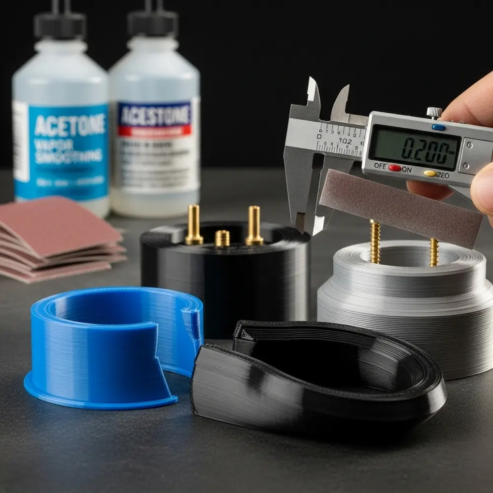
Designing for Post-Processing
Consider finishing operations during design. If parts will be sanded smooth, design thicker walls to withstand material removal. The Sinterit guide specifically mentions: “Increase wall thickness for functional parts or objects that require post-processing (like sanding or polishing)”. Parts intended for painting, vapor smoothing, or other finishing benefit from design choices accommodating these processes.
Conclusion
Learning how to design for 3D printing transforms 3D modeling from purely digital art into practical manufacturing capability. The principles explored here—understanding layer-by-layer construction’s impact on strength, respecting minimum wall thickness and feature size limitations, designing geometry to minimize support requirements, and creating watertight manifold meshes—distinguish printable designs from beautiful but unbuildable models. From my early failures with undersized walls and poor layer orientation through countless successful functional prints, the learning curve remains constant: 3D printing rewards designs created with the process in mind, not despite it.
The comprehensive coverage provided here—from software selection and fundamental design principles through optimization strategies and advanced techniques—provides foundational knowledge for creating successful 3D prints. But this pillar article only scratches the surface. Our cluster articles dive deeper into specific aspects: how to design 3D models for printing explores software options from beginner Tinkercad through professional Fusion 360, comparing parametric CAD against organic modeling approaches; how to make 3D print designs details essential rules for wall thickness, overhang management, tolerance design for assemblies, and articulated prints with moving parts; how to design your own 3D prints covers advanced techniques including custom mechanical designs, artistic applications, and troubleshooting common printability issues; and for those interested in the hardware side, how to design a 3D printer explores custom printer builds and modifications. Together, these resources provide comprehensive understanding of 3D printing design from concept through physical realization.


