
How to Design Your Own 3D Prints: Advanced Tips, Articulation, and Customization
Table of Contents
The action figure’s arm rotated smoothly through a full 360 degrees, the ball joint moving with just the right amount of resistance—firm enough to hold poses, loose enough to adjust easily. I watched in satisfaction as my first fully articulated 3D printed character passed the “playability test”. Six months earlier, I couldn’t have imagined designing something this mechanically sophisticated. My early attempts at articulated joints resulted in either fused-together parts that wouldn’t move at all or sloppy connections flopping uselessly. The breakthrough came when I stopped thinking of 3D printing as “making plastic shapes” and started understanding it as designing mechanical systems that happen to be manufactured additively. Learning how to design your own 3D prints at this advanced level—creating parts with intentional movement, customizing parametric designs for specific needs, integrating electronics into printed enclosures, and developing functional mechanical assemblies—requires moving beyond basic modeling into systematic engineering thinking. This isn’t about following tutorials to recreate others’ designs; it’s about understanding principles that enable you to solve unique problems and create exactly what you envision.
How to design your own 3D prints successfully at advanced levels demands understanding specialized techniques spanning multiple disciplines. Articulated joints—hinges, ball joints, sliders, and living hinges—require precise clearance calculations, material selection matching intended flexibility, and assembly strategies ranging from print-in-place to post-print assembly. Parametric customization enables creating base designs that users can modify for their specific measurements, preferences, or applications without redesigning from scratch. Functional enclosure design for electronics integrates mounting posts, cable management, ventilation requirements, and access panels into cohesive housings protecting circuits while enabling maintenance. And advanced mechanical designs incorporate gears, bearings, cam mechanisms, and other machine elements into printed assemblies. As explored in our comprehensive pillar guide on how to design for 3D printing, these advanced applications build upon fundamental principles while adding layers of mechanical, ergonomic, and functional complexity.
This advanced guide explores sophisticated techniques for how to design your own 3D prints, covering articulated joint design from basic hinges through complex ball joints, parametric design enabling mass customization, functional enclosure design for electronics and mechanical assemblies, advanced modeling techniques including living hinges and flexible components, and practical workflows from concept through functional prototypes. Whether creating articulated toys and figures, developing custom-fitted products, designing protective enclosures, or building functional mechanical assemblies, this guide provides the specialized knowledge needed to transform ambitious concepts into working 3D printed reality. For foundational design rules ensuring these complex designs remain printable, see our article on how to make 3D print designs, and for software recommendations supporting advanced techniques, explore our guide on how to design 3D models for printing.
Understanding Articulated Design Fundamentals
Before diving into specific joint types, understanding the principles underlying successful articulated designs prevents common failures.
Planning Degrees of Freedom
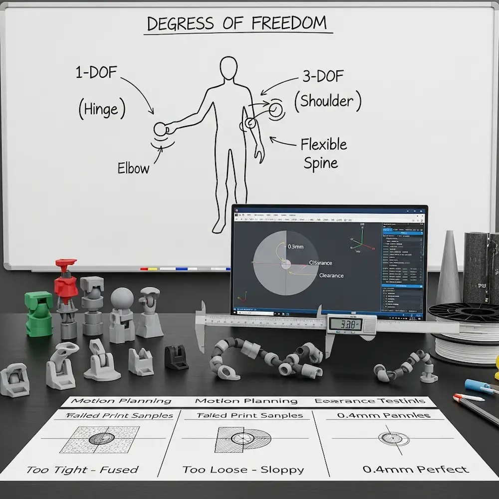
Degrees of freedom define how many independent movements your design allows. The 3D4Create guide emphasizes: “Degrees of Freedom – How many points will your model move and pivot? Plan out the types of motions needed”. A simple door hinge has one degree of freedom (rotation around a single axis). A shoulder joint might need three (rotation in multiple planes). A flexible spine might need continuous articulation along its length.
Motion planning shapes joint selection. The Creality Cloud guide explains: “Articulated 3D models are designed with movable joints that allow parts of the object to move or flex independently”. If your design needs rotation around a single axis, use hinge joints. For multi-axis rotation, ball joints work better. For bending flexibility, consider living hinges or chain joints. Planning these movements before modeling prevents designing incompatible joint types.
Material Selection for Articulation
Material flexibility dramatically affects joint performance. The 3D4Create article notes: “Material Choice – Flexible filaments such as silk PLA, TPU, and PLA allow more movement but can be trickier to print. Rigid materials hold alignment better”. Standard PLA works well for rigid ball joints and hinges requiring defined positions. TPU and flexible filaments enable living hinges and soft joints but demand specialized print settings.
Combining materials in a single design leverages each material’s strengths. Rigid components in PLA for structure, flexible sections in TPU for hinges, and post-print hardware (metal pins, screws) for high-stress pivot points create hybrid assemblies exceeding single-material capabilities.
Critical Clearance Calculations
Clearances determine success or failure of articulated designs. As our design rules article explored, proper clearances allow movement without binding while preventing excessive slop. The 3D4Create guide emphasizes: “Clearances – Joints need enough gap to move freely without too much slop and instability”.
Joint-specific clearances vary by type:
- Basic hinges: 0.3-0.4mm radial clearance
- Ball joints: 0.4-0.6mm clearance for smooth rotation
- Print-in-place chains: 0.5mm+ clearance to prevent fusion
- Sliders: 0.2-0.3mm for smooth linear motion
Testing different clearances on small prototypes before committing to full designs saves material and time.
Designing Ball Joints for 3D Printing
Ball joints enable multi-axis rotation critical for shoulders, hips, and swivel connections in articulated figures.
Ball Joint Geometry and Proportions
The Fusion 360 ball joint tutorial demonstrates professional techniques. The video “Mini Tutorial 1: Modeling a Ball Joint in Fusion 360” explains: “I share how I design ball joints for 3D printable action figures in Fusion 360. This design shows up in all of my articulated prints”. While specific dimensions depend on scale, proportional relationships remain consistent.
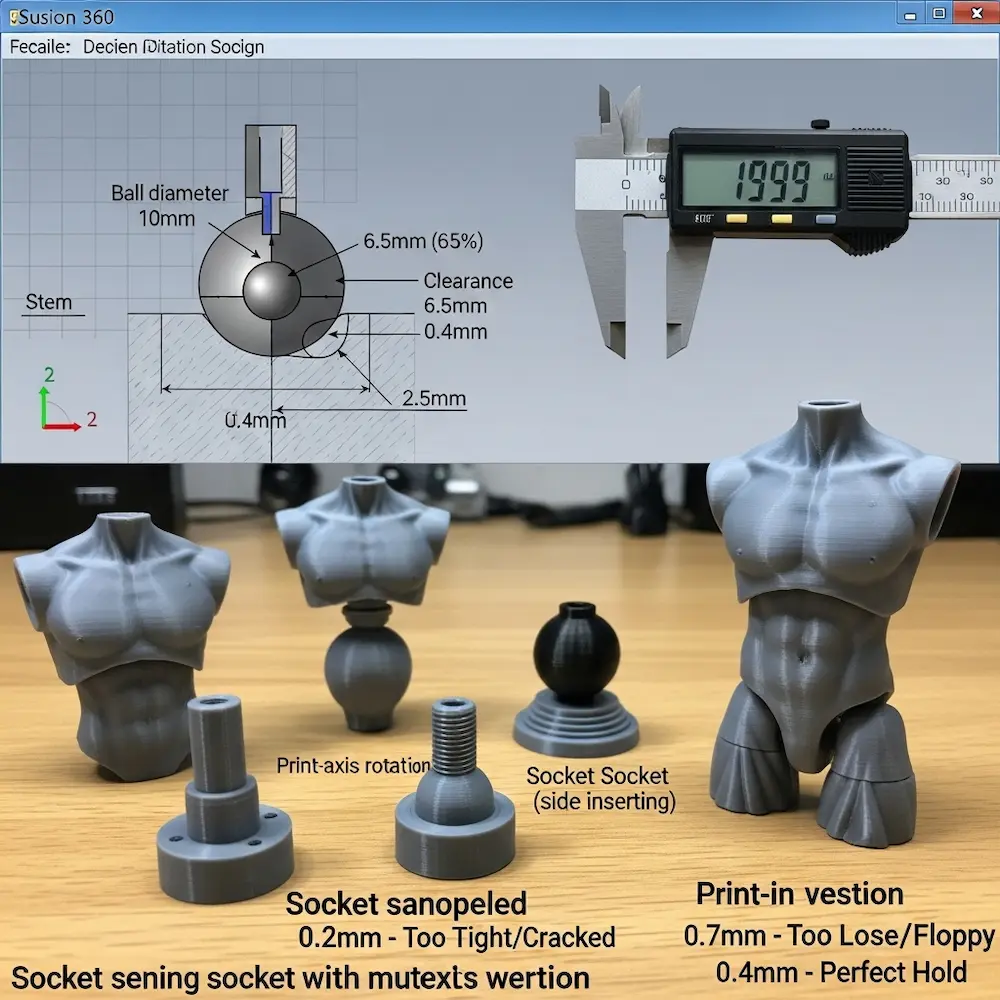
Socket depth typically equals 60-70% of ball diameter. Too shallow and the ball pops out easily; too deep and rotation becomes restricted. The socket opening must be smaller than ball diameter to retain it while allowing insertion through snap-fit assembly or print-in-place clearances.
Ball stem attachment requires sufficient thickness to prevent breaking. The stem connecting the ball to its limb or component should be at least 2.0mm diameter minimum, thicker for larger joints experiencing greater forces. The transition from stem to ball benefits from filleting (rounding) to reduce stress concentrations.
Socket Design Considerations
Multi-part versus print-in-place approaches each have advantages. Multi-part designs allow easier ball insertion and tighter fits but require assembly. The Creality guide discusses: “Assembly – Multi-part prints often require assembly after printing. Plan connection points”. Print-in-place sockets must include larger clearances (0.5-0.6mm) but print as complete assemblies.
Socket retention features prevent ball escape while allowing rotation. Common approaches include narrowed openings creating snap-fit retention, C-shaped sockets allowing ball insertion from the side, and split sockets that assemble around the ball post-print.
Friction and Hold Strength
Clearance directly controls friction. Tighter clearances (0.3-0.4mm) create joints holding positions firmly—ideal for posed figures. Looser clearances (0.5-0.6mm) enable smooth swiveling but may not hold poses against gravity. The MakerBuildIt guide notes the importance of “Ensure that the pieces are not touching each other to allow proper movement”.
Surface texture affects friction. Rough printed surfaces (from visible layer lines) create more friction than smooth surfaces (from higher resolution or post-processing). Some designers intentionally texture socket interiors for better grip.
Hinge Joint Design Techniques
Hinges—the simplest articulated joints—enable single-axis rotation for elbows, knees, and door-like movements.
Basic Cylindrical Hinge Construction
Pin-and-socket hinges represent the fundamental approach. The 3D4Create guide describes: “Basic Hinges – The simplest joints use circular pivots inserted into looped sockets”. A cylindrical pin fits into a cylindrical hole with appropriate clearance for rotation.
Design steps from our previous cluster article on articulating joints detail the process:
- Create cylindrical pin (minimum 2.0mm diameter for strength)
- Design matching cylindrical socket with 0.3-0.4mm radial clearance
- Add retention features (end caps, snap-fits) preventing pin escape
- Ensure adequate wall thickness around socket (2.0mm minimum)
The YouTube tutorial “Easy Articulating Joints for 3D Printing Anyone Can Make!” demonstrates two methods: “The Cutaway Joint” and “The Sidewall Joint,” both using cylinders and spheres. These approaches show practical implementation of theoretical principles.
Print-in-Place Chain Joints
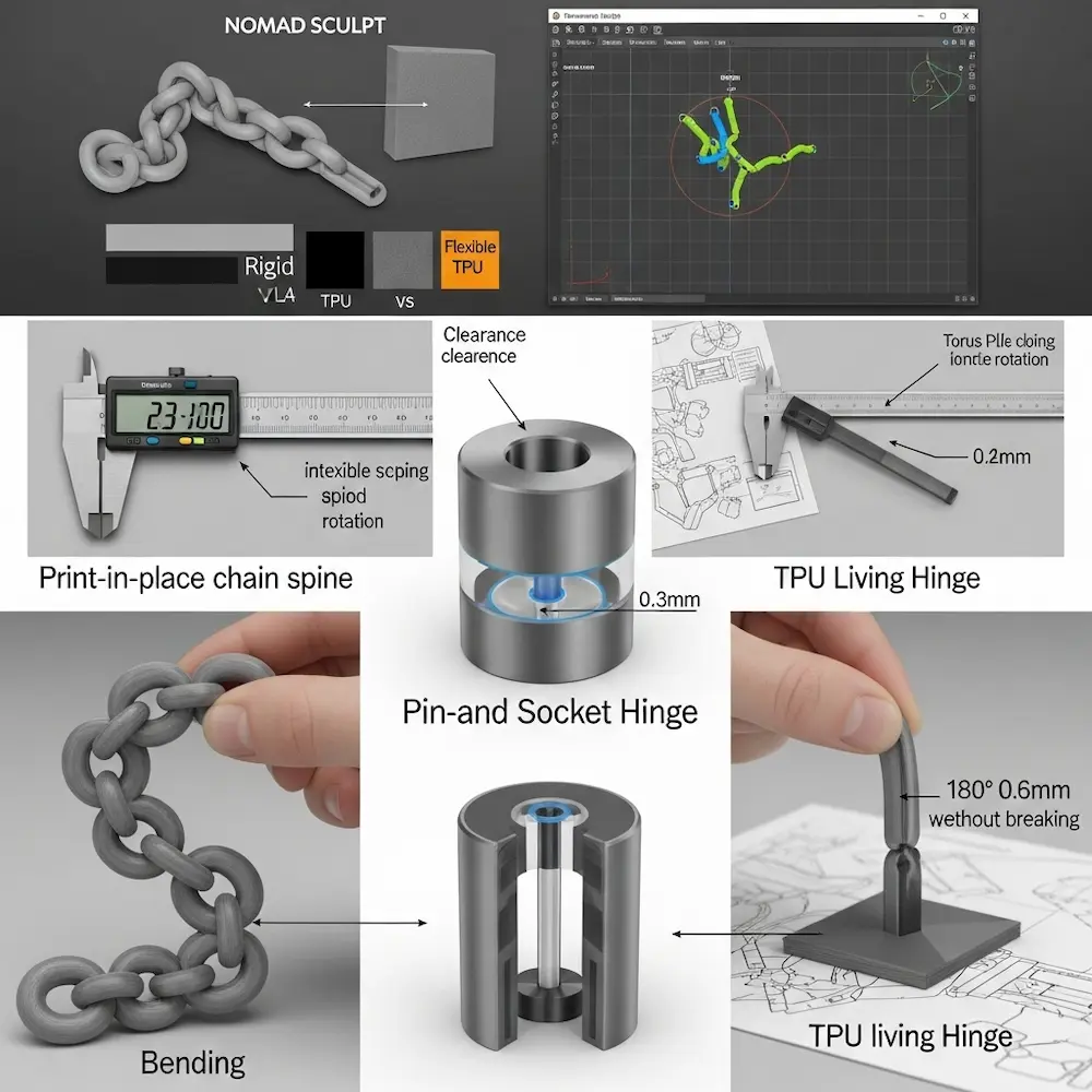
Chain joints create flexible spines and bendable sections through multiple interlocking links. The MakerBuildIt tutorial demonstrates “Creating a Flexi Joint in Nomad Sculpt” showing practical techniques.
Design workflow from the tutorial:
- Add base structure: “Start by adding a neck using the cylinder tool”
- Create connecting elements: “Use a chain joint to connect these two parts. Add a torus and adjust its size to fit the neck”
- Interlock components: “Clone the torus and move it slightly. Rotate it 90 degrees to create an interlocking effect”
- Ensure clearance: “Ensure that the pieces are not touching each other to allow proper movement”
Critical spacing: Chain links need 0.5mm or more clearance between adjacent links to prevent fusion during printing. Layer-by-layer deposition can cause slight material overlap if clearances are insufficient.
Living Hinges: Flexible Material Joints
Living hinges use thin, flexible sections of material itself as hinges rather than mechanical joints. The 3D4Create guide explains: “Living Hinges – Thin, flexible sections in the model itself act as hinges”. This approach works particularly well with flexible filaments like TPU.
Design parameters for living hinges include hinge thickness (typically 0.4-0.8mm for TPU, 0.6-1.0mm for flexible PLA), hinge length (affects flex radius—longer distributes bending), and print orientation (layers should run perpendicular to bend direction for flexibility). Living hinges excel for applications like flip-top closures, flexible grippers, or compliant mechanisms.
Parametric Design for Customization
Parametric modeling enables creating adjustable designs users can customize for their specific needs without CAD expertise.
Understanding Parametric Workflows
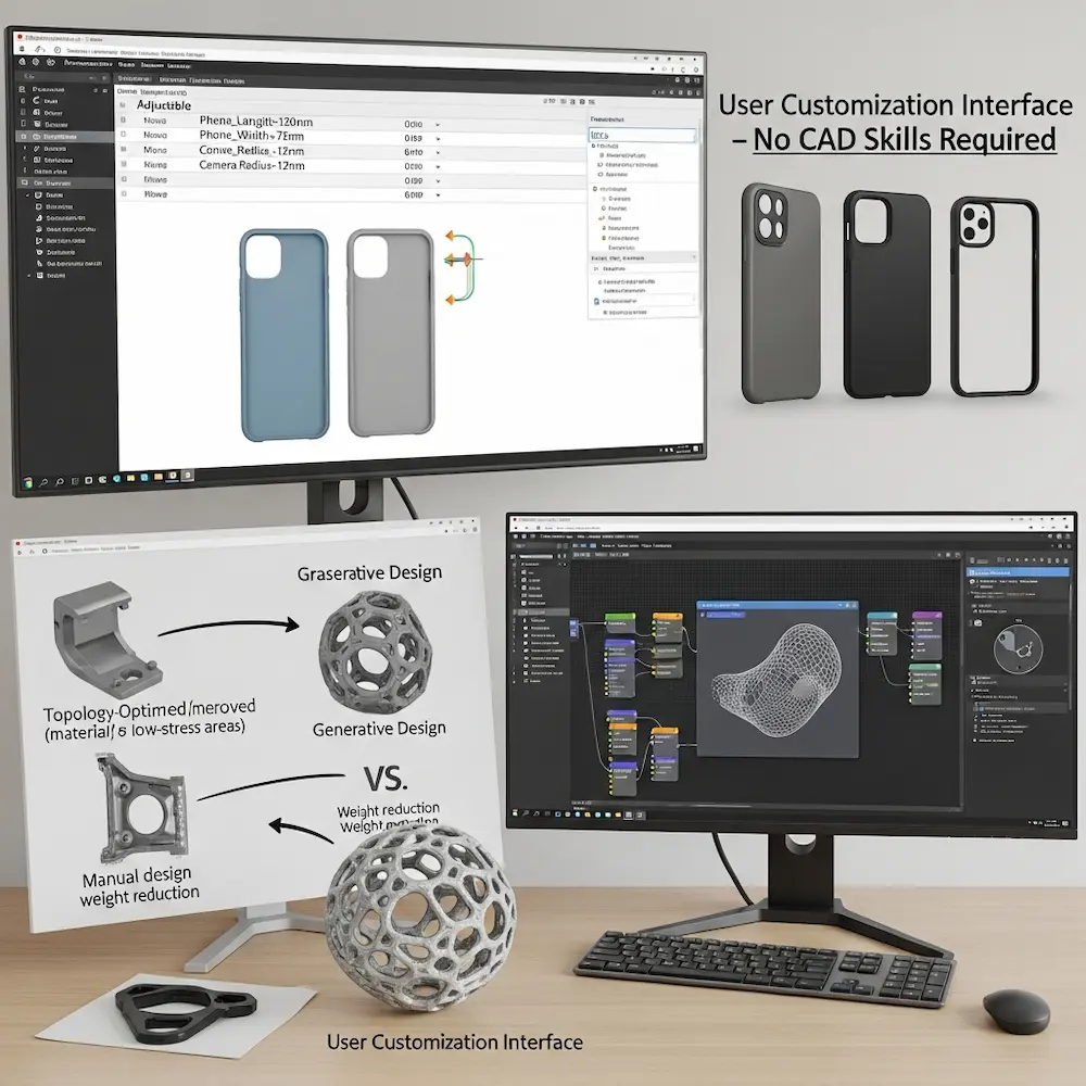
Variable-driven design defines models through adjustable parameters rather than fixed dimensions. The Kreate 3D article explains: “Flexible Design Modification – Parametric design allows for the creation of 3D models with adjustable parameters. Designers can define variables such as dimensions, shapes, and patterns, making it easy to modify the design based on specific requirements without having to redesign the entire model”.
Practical example: Instead of designing a phone case for one specific phone model, create a parametric design with variables for phone length, width, thickness, camera position, and button locations. Users input their phone’s measurements, and the model regenerates automatically. This single design serves hundreds of phone models.
Creating Adaptive Designs
Responsive parameters enable designs adapting to external constraints. The Kreate article describes: “Adaptive and Responsive Designs – Parametric models can be designed to respond to external factors or constraints. For example, a parametric design for a chair may adapt its structure based on the user’s body dimensions, creating a customized and ergonomic solution”.
Personalization at scale: The academic study on “Personalization Process of 3D Printed Products using Parametric Design” proposes methods “to reduce the designer’s involvement and to give control to the user during the product design process”. This democratizes design—non-experts can create customized objects through simple parameter adjustment.
Generative and Algorithmic Design
Generative algorithms create complex forms based on defined rules. Kreate 3D notes: “Generative Algorithms – Parametric design often involves the use of generative algorithms that generate complex shapes and structures based on predefined rules. This is particularly advantageous for creating intricate, organic, or highly detailed designs that may be challenging or time-consuming to model manually”.
Applications include lattice structures optimized for strength-to-weight ratios, organic forms mimicking natural growth patterns, and topologically optimized parts removing material from non-stressed areas. These algorithmic approaches create designs impossible through traditional manual modeling.
Software for Parametric 3D Printing
Fusion 360’s parametric capabilities make it ideal for customizable designs. The parameter table lets you define variables users can adjust. Grasshopper for Rhino offers visual programming for complex parametric models. OpenSCAD’s code-based approach provides ultimate parametric control for programmers. Our software article explores these tools comprehensively.
Designing Functional Enclosures for Electronics
Custom 3D printed enclosures protect electronics while providing access and functionality.
Planning Enclosure Layout
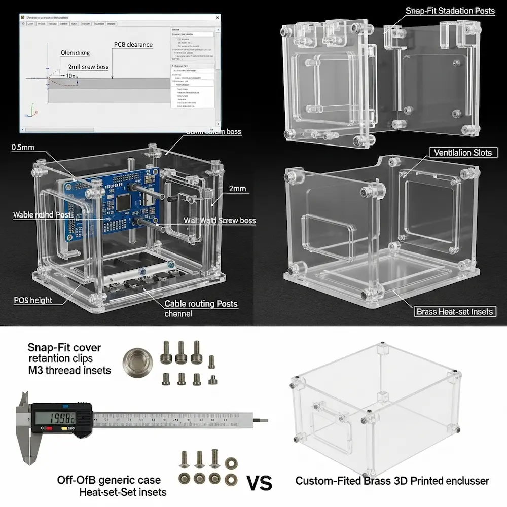
Internal component arrangement determines enclosure geometry. The JLC3DP guide explains: “3D printing allows you to create a custom design based on the unique needs of your device, precisely fitting ports, mounting points, and internal layout, thereby solving the mismatch issues of traditional off-the-shelf enclosures”.
Design considerations include:
- PCB mounting points and standoffs
- Cable routing paths and strain relief
- Battery compartment dimensions and access
- Display cutouts and viewing angles
- Button access or integrated button extensions
- Ventilation requirements for heat dissipation
- Assembly method (snap-fit, screws, or glued)
Measurement precision: Measure actual PCB dimensions and component positions carefully. Circuit boards often differ slightly from published specifications. Design enclosures with 0.5-1.0mm clearance around boards for assembly tolerance.
Mounting Posts and Standoffs
PCB mounting typically uses standoff posts with threaded inserts or screw bosses. The Sculpteo guide notes: “3D printing is also giving you the opportunity to be more innovative and improve your enclosures designs. This way, you will be able to create plastic PCB enclosures perfectly adapted to your projects”.
Design specifications:
- Post diameter: 5-8mm for M3 screws (most common PCB mounting)
- Wall thickness around screw hole: 2.0mm minimum
- Post height: PCB thickness + component clearance (typically 8-12mm)
- Fillet at base: 0.5-1.0mm radius for strength
Heat-set inserts provide robust metal threading in plastic posts. Design holes 0.1-0.2mm smaller than insert diameter for press-fit installation with soldering iron.
Access Panels and Assembly
Multi-part enclosures balance protection with serviceability. Common approaches include hinged lids with living hinges or mechanical hinges, snap-fit covers with retention clips, screwed covers with threaded bosses, and sliding panels in grooves.
Cable management integrates strain relief and routing. Design cable exit ports slightly larger than cable diameter (1-2mm clearance), add internal channels guiding cables to ports, and incorporate strain relief features preventing cable damage.
Ventilation and Thermal Management
Heat dissipation requires thoughtful ventilation design. Electronic components generate heat that accumulates in sealed enclosures. Design perforated panels or vent slots near heat-generating components, create airflow paths from bottom to top enabling convection, and ensure vent geometry maintains structural integrity (bars between holes for strength).
Material Selection for Enclosures
Appropriate materials vary by application. Sculpteo’s guide recommends: “Plastic electronic enclosures can be developed using additive manufacturing with adapted materials. To create these plastic enclosures, 3D printing materials such as Nylon PA12 or Nylon PA11 will be especially suitable for your project”. Standard PLA works for indoor, room-temperature applications. PETG offers better impact resistance. Nylon provides superior durability for professional products.
Advanced Modeling Techniques
Beyond basic CAD operations, advanced techniques create sophisticated functional designs.
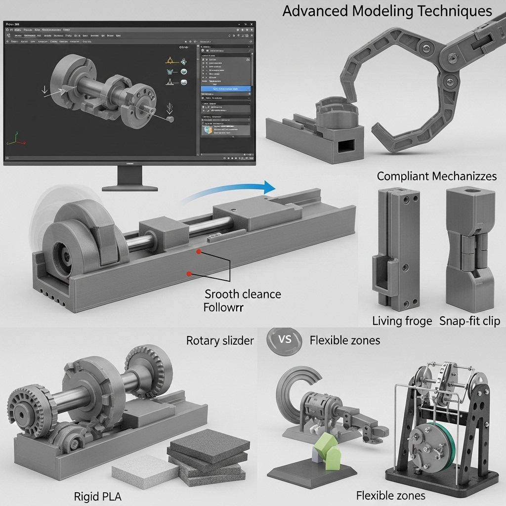
Sliders and Linear Motion
Linear sliders enable straight-line motion for drawer mechanisms, adjustable components, and linear actuators. The 3D4Create guide lists “Sliders and Pivots – Linear sliders, ball joints, and cams can create more complex motions”.
Design requirements:
- Slide rails: rectangular profiles providing guidance
- Clearance: 0.3-0.4mm on each side for smooth sliding
- Retention: end stops or snap features preventing separation
- Low-friction surfaces: print orientation minimizing layer-line drag
Cam Mechanisms and Mechanical Advantage
Cam profiles convert rotary motion to specific output movements. Rotating a cam with an irregular profile pushes followers in programmed patterns. These mechanisms create complex motions from simple inputs, useful in automata, mechanical toys, and functional devices.
Flexible Components and Compliant Mechanisms
Compliant mechanisms achieve motion through elastic deformation rather than traditional joints. The 3D4Create article mentions: “Flexible Components – Use bending designs for softer parts like fingers or spinal joints”. Applications include living hinges, snap-fits, spring mechanisms, and gripper fingers.
Design considerations: Material choice (flexible filaments excel), feature thickness (thinner sections flex more easily), print orientation (layers affect flex direction), and stress concentration management (fillets at flex points).
Printing and Assembly Best Practices
Even perfect designs fail without proper printing and assembly techniques.
Print Settings for Articulated Designs
Optimized settings from the 3D4Create guide include:
Supports and Orientation: “Minimize overhangs and angles that require supports inside joints”. Supports inside joint clearances fuse components together, requiring careful removal. Orienting parts to minimize internal supports prevents this issue.
Layer Adhesion: “Small layer heights and adjusted temperatures promote part strength”. Articulated parts experience mechanical stress at joints; strong layer adhesion prevents delamination.
Infill Settings: “Higher infills or strategic patterns give the structure integrity”. Joint areas benefit from increased infill (40-50%) even if overall model uses lower percentages.
Assembly Techniques
Post-print assembly offers advantages over print-in-place for complex designs. The Creality guide discusses: “Multi-part prints often require assembly after printing. Plan connection points”.
Hardware integration: “Insert nuts and bolts for sturdy but movable connections”. Metal fasteners provide superior durability for high-stress joints compared to purely plastic connections.
Testing and Iteration
Prototype small sections before printing full designs. Test a single joint design first, verifying clearances and fit before committing to complete assemblies. The Creality guide emphasizes: “Before diving into the design process, it’s helpful to sketch out your ideas and identify the key moving parts and joints needed”. This planning prevents expensive full-print failures.
Conclusion
Learning how to design your own 3D prints at advanced levels transforms 3D printing from making simple static objects into creating sophisticated mechanical systems, customizable products, and functional devices. From my early frustrated attempts at articulated joints through developing working ball-jointed figures, the progression required understanding that successful advanced designs integrate mechanical engineering principles with manufacturing process knowledge. Articulated joints demand precise clearance calculations matching material properties and intended movement. Parametric design enables mass customization by defining designs through adjustable variables rather than fixed dimensions. Electronic enclosures integrate mounting, access, ventilation, and assembly into cohesive protective housings. And advanced mechanical techniques including sliders, cams, and compliant mechanisms create complex functional assemblies.
The specialized techniques explored here—from ball joint geometry and hinge design through parametric customization workflows, functional enclosure planning, and assembly best practices—represent the frontier of hobbyist and professional 3D printing capabilities. These aren’t theoretical exercises but practical skills enabling creation of products, prototypes, and functional objects impossible through traditional manufacturing or basic 3D printing approaches. For foundational understanding of design principles supporting these advanced techniques, explore our pillar guide on how to design for 3D printing covering core concepts. For technical specifications ensuring complex designs remain printable, see our article on how to make 3D print designs detailing wall thickness, tolerances, and design rules. And for software recommendations supporting advanced parametric and articulated design, consult our guide on how to design 3D models for printing comparing tools from beginner to professional levels. Together, these resources provide complete knowledge for transforming ambitious concepts into functional 3D printed reality.


