
How to Make 3D Print Designs: Essential Rules for Successful Prints
Table of Contents
The print finished after six hours, and I eagerly removed what should have been a custom gear assembly from the build plate. The main body looked perfect—clean layers, smooth surfaces, proper dimensions. But when I tried to insert the axle into the center hole I’d so carefully designed, it wouldn’t fit. Not even close. I’d modeled a 5mm hole expecting a 5mm shaft to slide through smoothly, but the printed hole measured barely 4.7mm. The plastic had expanded slightly during printing, shrinking the opening. Worse, the thin support arms connecting the gear teeth had snapped off during removal because I’d designed them only 0.6mm thick—below the practical minimum for FDM printing. That expensive failure taught me what every experienced 3D printing designer learns eventually: beautiful CAD models don’t automatically become successful prints. Understanding how to make 3D print designs requires mastering rules that bridge the gap between digital perfection and physical reality—minimum wall thicknesses that prevent fragile features, overhang angles that determine support requirements, tolerance clearances that allow parts to actually fit together, and design strategies that work with the printing process rather than against it. These aren’t arbitrary restrictions limiting creativity; they’re physical realities enabling functional designs.
Learning how to make 3D print designs successfully means understanding that 3D printing’s layer-by-layer construction creates specific limitations and opportunities fundamentally different from traditional manufacturing or pure digital modeling. The most common design failures stem from ignoring these principles: walls too thin to print reliably, overhangs extending beyond the printer’s capabilities without support, holes and clearances designed without accounting for printing tolerances, and features below the minimum resolution the printer can reliably produce. Yet understanding and applying these rules doesn’t constrain creativity—it enables it. Knowing that overhangs beyond 45 degrees need support lets you design self-supporting geometry. Understanding minimum wall thickness (0.8-1.2mm for FDM) helps you create structures that are both printable and strong. Mastering tolerance design allows you to create assemblies with moving parts that snap together perfectly on the first try. As explored in our comprehensive pillar guide on how to design for 3D printing, these technical requirements shape every design decision from initial concept through final file preparation.
This essential guide explores the fundamental rules for how to make 3D print designs that actually work, covering wall thickness requirements for different applications, overhang management and support strategies, tolerance design for assemblies and moving parts, resolution limits and minimum feature sizes, design optimization for strength and printability, and specialized techniques for articulated prints with joints and hinges. Whether you’re creating your first simple functional object wondering how to design something for 3D printing, developing complex mechanical assemblies, or troubleshooting why your designs keep failing, this guide provides the technical knowledge needed to design models that print successfully and perform their intended functions. For software-specific guidance, see our article on how to design 3D models for printing, and for advanced customization techniques, explore our guide on how to design your own 3D prints.
Wall Thickness: The Foundation of Printable Designs
Wall thickness represents perhaps the single most critical design parameter determining whether models print successfully or fail catastrophically.
Understanding Minimum Wall Thickness
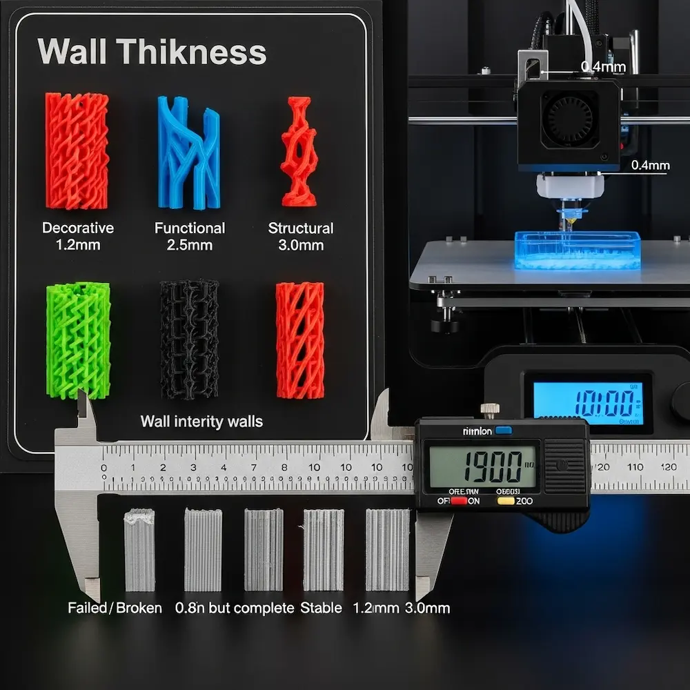
Technology-specific minimums vary based on printing method and material. Sinterit’s comprehensive wall thickness guide provides detailed specifications: “FDM (PLA/ABS): ~0.8–1.2 mm, SLA/DLP: ~0.5 mm, SLS (Nylon PA12): ~0.7 mm for vertical walls, 1 mm for unsupported, DMLS (metal): ~1–2 mm”. These minimums reflect each technology’s physical limitations. For the most common consumer FDM printers using 0.4mm nozzles, practical minimum wall thickness is 0.8mm—exactly twice the nozzle diameter.
The fundamental rule: Raise3D’s wall thickness guide states clearly: “The minimum wall thickness should be at least twice the nozzle diameter to ensure proper adhesion and strength. For example, if you are using a nozzle with a diameter of 0.4 mm, the recommended minimum wall thickness would be 0.8 mm or more”. This doubling ensures the printer can lay down at least two perimeter passes, creating structural integrity. Single-wall prints (one nozzle width) are fragile and prone to gaps.
Why minimums matter physically: Walls below minimum thickness face multiple failure modes. The printer struggles to deposit plastic consistently in ultra-thin spaces, creating gaps or missing sections. Thin walls lack structural strength, breaking during printing, removal, or use. Temperature management becomes problematic—thin features heat and cool rapidly, leading to warping. The Sinterit guide emphasizes: “Avoid long, thin, unsupported vertical or horizontal walls — they tend to warp or break easily”.
Recommended Thickness by Application
Application-specific guidelines balance strength, weight, material cost, and print time. Mandarin3D’s practical table provides clear recommendations:
| Feature Type | Minimum | Recommended |
|---|---|---|
| General walls | 0.8mm | 1.2mm+ |
| Structural walls | 1.2mm | 2.0mm+ |
| Protruding pins/pegs | 2.0mm | 3.0mm+ |
| Thin vertical features | 1.0mm | 1.5mm+ |
Decorative versus functional parts require different approaches. Decorative models that won’t experience stress can use thinner walls (1.0-1.5mm) with lower infill percentages (10-20%). Functional parts experiencing mechanical loads need thicker walls (2.0-3.0mm or more) with higher infill (30-50%+). The Xometry design guide recommends: “Design walls at least 1.00-1.50 mm thick, or three times the nozzle diameter”. This three-times rule provides safety margin beyond the two-times minimum.
Unsupported versus supported walls have different requirements. The HLH Rapid guide specifies: “Unsupported walls—connected to the rest of the print on less than two sides—are at a high risk of warping. To avoid this, they should be at least 1.2mm thick” while “Supported Walls” need “At least 1.0mm thick”. Walls connected on multiple sides gain stability from surrounding structure; cantilevered walls extending into space need extra thickness to resist bending.
Best Practices for Wall Thickness Design
Design strategies from Sinterit’s guide include practical recommendations:
- “Stick to 2–3 times the nozzle diameter (FDM) or laser spot size (SLS/DMLS) as a baseline”
- “Increase wall thickness for functional parts or objects that require post-processing (like sanding or polishing)”
- “Consider feature resolution and heat accumulation, especially for fine details”
Post-processing considerations: If parts will be sanded, polished, or machined after printing, design extra wall thickness to accommodate material removal. A 1.0mm wall becoming 0.7mm after aggressive sanding becomes structurally compromised.
Managing Overhangs and Supports
Overhangs—geometry extending outward without support directly below—represent 3D printing’s most visible design challenge.
The 45-Degree Rule and Overhang Limits
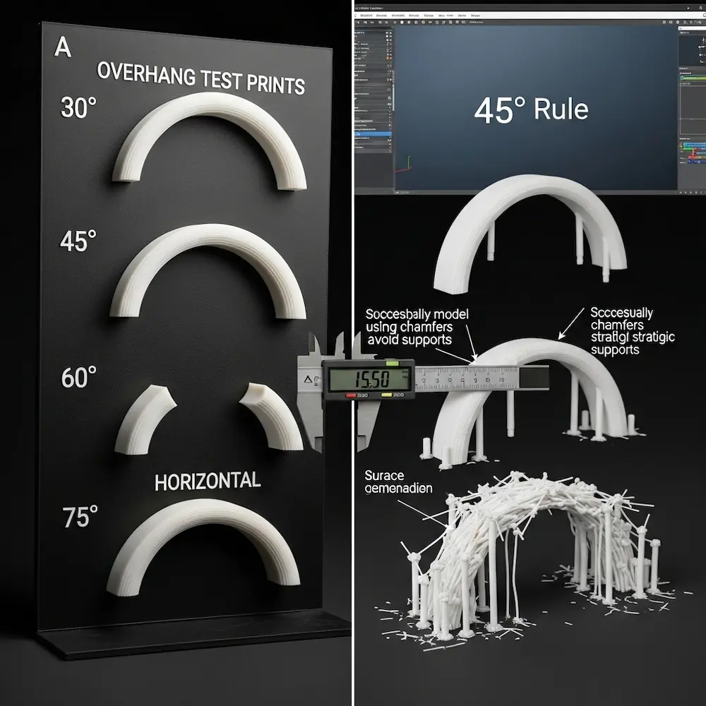
The fundamental principle: The HLH Rapid guide explains: “Depending on the material, an overhang can usually be printed up to 1.2mm in length and up to 45° without compromising quality. Anything above these limits will require support”. This 45-degree threshold (measured from horizontal) represents where most FDM printers transition from self-supporting to requiring support structures.
Why 45 degrees works: At shallower angles (more vertical), each new layer has sufficient previous layer underneath to bond properly. Beyond 45 degrees, new material lacks adequate foundation, sagging or failing completely. The Xometry guide states: “Overhangs exceeding the maximum overhang angle of 45° require support”. Some high-quality printers with excellent cooling can manage 50-55 degrees, but 45 degrees provides reliable safety margin.
Distance matters: Small overhangs under 1-2mm often print successfully even at steep angles because the plastic doesn’t have far to bridge. The HLH Rapid guide specifies “up to 1.2mm in length” as manageable without support regardless of angle. But larger overhangs following the angle rule become critical.
Design Strategies to Minimize Support Requirements
Geometric solutions reduce or eliminate support needs. Mandarin3D’s practical advice includes:
- “Keep overhangs at 45 degrees or less whenever possible”
- “Add chamfers instead of hard 90-degree edges on bottom surfaces”
- “Consider splitting the design and gluing parts after printing”
Orientation optimization: As emphasized in our pillar guide, print orientation dramatically affects support requirements. The same cylindrical part oriented vertically versus horizontally has radically different overhang profiles. Rotating parts to minimize overhangs eliminates supports while maintaining strength.
Bridging capabilities: Most FDM printers can “bridge” horizontal gaps spanning 5-10mm with properly tuned settings. The Xometry guide notes: “Bridges longer than 5 mm may need additional supports”. Designing with intentional bridges rather than angled overhangs can create self-supporting geometry.
When Supports Are Necessary
Support touch points should be designed intentionally. Rather than letting automatic support generation place supports randomly, design flat areas or attachment points where supports can be easily removed without damaging visible surfaces. Supports leave marks; controlling where they touch controls where imperfections appear.
Support removal considerations: Dense, complex supports are difficult to remove and often damage part surfaces. Simple, sparse supports with clear access remove cleanly. Design parts considering how supports will be accessed and removed.
Tolerance and Clearance for Assemblies
Designing parts that fit together requires understanding 3D printing tolerances—the inevitable dimensional variations between designed and actual printed dimensions.
Understanding 3D Printing Tolerances
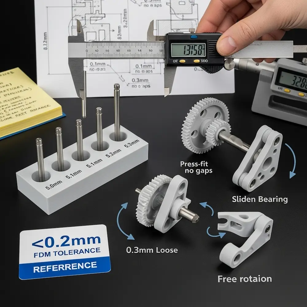
Achievable tolerance varies by technology. Assemblean’s design tips specify: “For FDM 3D-printing, the achievable tolerance is at least 0.3mm” while “In the DMLS process, parts are produced with tolerances of 0.1mm to 0.2mm”. Consumer FDM printers typically achieve ±0.1-0.3mm dimensional accuracy. This means a designed 10mm cube might actually measure 9.8-10.2mm.
Sources of dimensional variation include plastic shrinkage as it cools, layer adhesion imperfections, nozzle diameter affecting perimeter placement, and temperature fluctuations during printing. These variations are predictable and manageable through proper clearance design.
Clearance Guidelines for Different Fit Types
Fit classification determines required clearances. The eufyMake tolerance guide provides specific values: “For a tight fit, strive for a clearance gap of 0.005 in (or 0.127 mm). For a standard fit, it’s typically around 0.010 in (or 0.254 mm), and for a loose fit, it should be about 0.020 in (or 0.508 mm)”. These clearances account for both printing tolerances and desired fit characteristics.
Practical interpretation for FDM printing:
- Press fit (0.1-0.15mm clearance): Parts require force to assemble and won’t disassemble easily
- Sliding fit (0.2-0.3mm clearance): Parts slide together with light force and move smoothly
- Loose fit (0.4-0.5mm clearance): Parts assemble easily with visible gaps and free movement
HP Multi Jet Fusion example: The Assemblean guide notes: “The high accuracy of HP MJF 3D printing allows fully functional assemblies to be printed. Components require a minimum clearance of 0.4mm or 0.2mm respectively for a movable bearing and a clamped bearing”. Different technologies enable different precision levels.
Designing Holes and Shafts
The cardinal rule: Design holes slightly larger than needed and shafts slightly smaller. A 5mm shaft intended to fit a 5mm hole won’t work—the hole will print undersized due to material expansion, and the shaft will print oversized. Instead, design the hole at 5.2-5.3mm and the shaft at 4.9mm for a proper fit.
Testing and iteration: The eufyMake guide recommends: “Print calibration parts with various clearances to find optimal values for your specific printer and material combination”. A test piece with multiple hole sizes (5.0mm, 5.1mm, 5.2mm, 5.3mm) and a standard shaft reveals which clearance works best.
Designing Articulated Joints and Moving Parts
Creating articulated 3D prints with hinges, ball joints, and other moving connections requires specialized design techniques.
Hinge Joint Design
Basic hinge construction uses cylindrical pins fitting into cylindrical sockets. The YouTube tutorial “Easy Articulating Joints for 3D Printing Anyone Can Make!” demonstrates two methods: “The Cutaway Joint” and “The Sidewall Joint”. Both use cylinders and spheres to create pins that snap into matching receptacles.
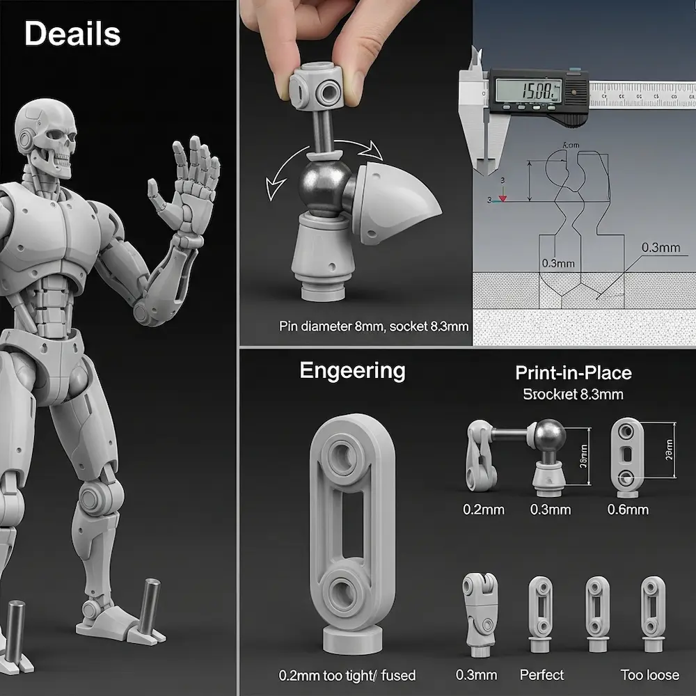
Critical clearances: The tutorial emphasizes: “Leave a small clearance between hinge parts to ensure smooth motion and avoid stress fractures during assembly”. Typical hinge clearances range from 0.3-0.5mm depending on desired tightness. Too little clearance and parts fuse together during printing or bind during movement; too much and joints become floppy.
Design approach: The video shows “Sculpting the thigh & shin, Adding hinge cylinders & spheres” and specifically notes you could “shrink down the size of the uh joint of the calf and that way it will fit in perfectly in the hinge”. This dimensional adjustment for proper clearance distinguishes functional articulated designs from non-functional attempts.
Ball Joint Design
Ball-and-socket joints enable multi-axis rotation for shoulders, hips, and swivel connections. The Facebook discussion asks: “What advice do you have for designing and printing hinge joints, ratcheting joints, and other articulation joints for 3D printed models?”, indicating active community interest in these techniques.
Design considerations for ball joints include sufficient clearance for rotation without binding (typically 0.4-0.6mm), adequate wall thickness on the socket to prevent cracking (2.0mm minimum), and snap-together assembly features or print-in-place designs. Our advanced techniques article explores how to design articulated 3D prints comprehensively.
Print-in-Place Mechanisms
Print-in-place designs create fully assembled mechanisms in a single print. Careful clearance design allows moving parts to separate after printing without disassembly. The Assemblean guide notes this requires “minimum clearance of 0.4mm” between components for HP MJF technology. FDM typically needs 0.5mm or more clearance for reliable print-in-place assemblies.
Resolution Limits and Minimum Feature Sizes
Not all designed details will print successfully—understanding resolution limits prevents designing unprintable features.
Minimum Feature Dimensions
Pins and protrusions have practical minimums. The HLH Rapid guide specifies: “Pins: Minimum reliable diameter is 1.0mm”. Mandarin3D recommends even thicker: “Protruding pins/pegs: 2.0mm Minimum, 3.0mm+ Recommended”. Thin pins below these minimums bend, break, or fail to print entirely.
Embossed and engraved text requires careful sizing. Text smaller than 1.5-2.0mm height becomes illegible or fills in during printing. Embossed (raised) text prints more reliably than engraved (recessed) text, which accumulates material and loses definition.
Layer height limitations: Features smaller than 2-3 layer heights become unreliable. Printing at 0.2mm layers means features below 0.4-0.6mm likely won’t resolve properly. Switching to 0.1mm layers improves detail resolution but doubles print time.
Detail Preservation Strategies
Design for your layer height: If printing at 0.2mm layers, avoid details smaller than 0.5mm. Scale features appropriately: Small decorative details should be proportionally larger than you might expect to ensure visibility. Test small: Print small test sections with critical details before committing to full-size prints.
Optimizing Designs for Strength and Efficiency
Beyond minimum printability, optimized designs balance strength, material efficiency, and print time.
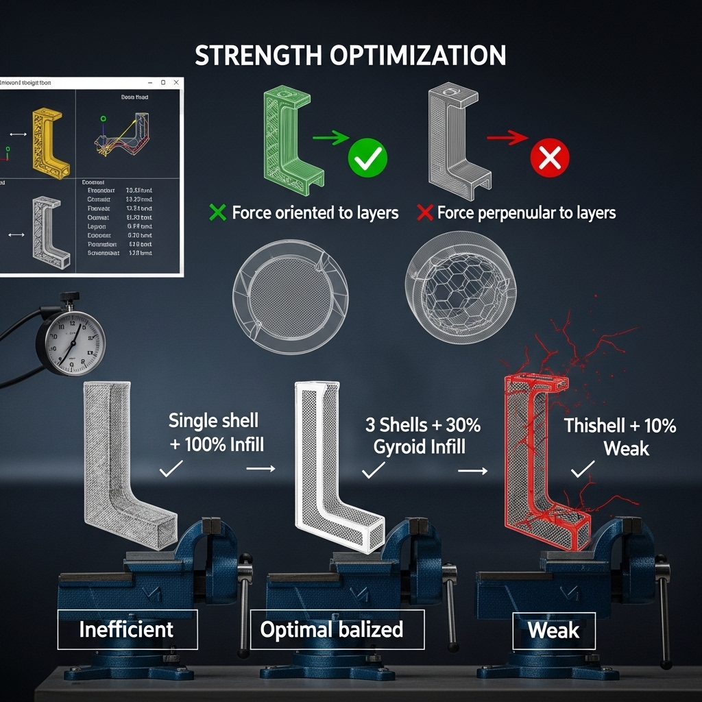
Infill and Shell Strategy
Shell count (number of perimeter walls) dramatically affects strength. Raise3D notes: “Infill overlap, or the percentage of overlap between the wall and the infill pattern, plays a role in determining wall thickness”. Using 3-4 shells with appropriate infill creates stronger parts than single-shell designs regardless of infill percentage.
Strategic infill: The Xometry guide recommends: “Use cross-hatch inner structures instead of solid walls to reduce material use and weight”. This maintains strength while reducing material and print time. Functional parts typically use 20-40% infill; structural components may need 50%+.
Stress Direction Consideration
Layer orientation affects strength: As emphasized in our pillar guide, parts are weaker between layers than within layers. Design orientation so that primary stresses run parallel to layers, not perpendicular. A hook experiencing pull forces should be oriented so layers run along the length, not across it.
Fiber direction in shells: The outer shell layers run perpendicular to each other (alternating directions each layer), creating cross-hatched strength. Orienting parts so stresses align with shell fiber direction maximizes strength.
Common Design Mistakes and How to Avoid Them
Understanding typical failures prevents repeating others’ expensive mistakes.
Mistake 1: Ignoring Minimum Wall Thickness
Symptom: Thin walls with holes, gaps, or complete failures during printing. Solution: Always check wall thickness before exporting. Most CAD software includes measurement tools. Ensure all walls meet or exceed 0.8mm minimum (1.2mm+ recommended).
Mistake 2: Designing Without Clearances
Symptom: Assemblies that won’t fit together despite “perfect” CAD dimensions. Solution: Add 0.2-0.3mm clearance to all mating surfaces. Design holes 0.2-0.3mm larger than shafts they receive. Test with calibration prints before finalizing designs.
Mistake 3: Excessive Overhangs Without Support Planning
Symptom: Sagging surfaces, drooping features, or complete print failures on overhanging sections. Solution: Keep overhangs under 45 degrees whenever possible. Add chamfers to reduce overhang angles. Design support touch points on non-visible surfaces.
Mistake 4: Features Below Minimum Resolution
Symptom: Tiny details that don’t appear in prints or blur together. Solution: Keep all features at least 1.0mm thick for visibility. Make text at least 2.0mm tall. Design details proportionally larger than you might intuitively expect.
Conclusion
Learning how to make 3D print designs that actually work requires mastering fundamental rules bridging digital models and physical reality. From my early failures with undersized clearances and too-thin walls through countless successful functional prints, the lesson remains constant: these rules aren’t arbitrary restrictions—they’re enabling constraints that make ambitious designs possible. Understanding that FDM printing requires 0.8-1.2mm minimum wall thickness prevents fragile features destined to break. Respecting the 45-degree overhang rule enables self-supporting geometry eliminating support headaches. Designing with 0.2-0.3mm clearances ensures assemblies actually fit together on the first print. And accounting for minimum feature sizes prevents designing unprintable details.
The comprehensive coverage here—from wall thickness specifications and overhang management through tolerance design for assemblies, articulated joint construction, and resolution limitations—provides the technical foundation for successful 3D printing design. These principles apply regardless of what software you use or what you’re designing. For software-specific guidance on implementing these rules, explore our article on how to design 3D models for printing comparing tools from Tinkercad through professional CAD. For comprehensive context on why these rules matter, see our pillar guide on how to design for 3D printing covering fundamental processes and principles. And for advanced applications including complex articulated prints and custom mechanical designs, consult our guide on how to design your own 3D prints. Together, these resources ensure your designs achieve both technical printability and functional success.


